RV Inverter Sizing & Wiring Guide (2026): Fuse Rule, Wire Gauge, and Safety Checklist
Affiliate disclosure
Some links may be affiliate links. If you buy through them, RVOutfitting.com may earn a commission at no extra cost to you.
Above-the-Fold “Quick Answer”
Quick Answer Box
- Size by real loads: add up continuous watts plus surge watts for what runs at the same time.
- The DC side is the fire-risk zone: cable + lugs + fuse + disconnect must match the inverter’s current.
- Put overcurrent protection near the battery/source: keep the unprotected conductor as short as practical.
- Wire gauge depends on amps + length + allowed voltage drop: don’t guess—use voltage-drop sizing tools/charts.
- Inverter/charger manuals often specify the DC fuse + cable size—treat that as final authority.
- Neutral–ground bonding behavior varies by model (often via internal relay): follow your exact manual to avoid GFCI/RCD weirdness.
“Sizing in 60 seconds”
- Make a load list (what runs together, in watts).
- Account for surge (microwave, compressor fridge, pump).
- Convert AC watts → DC amps, then size cable + fuse using the manufacturer table.
Fundamentals (Confusion Killer)
RV Inverter vs Converter vs Inverter/Charger — what’s the difference?
- Inverter: DC → AC (battery power becomes household-style AC power).
- Converter/charger: AC → DC (shore/generator power runs 12V loads and charges the battery).
- Inverter/charger: combines inverter + charger and usually includes pass-through/transfer so shore/gen can feed your panel while charging. (How this is implemented is model-specific—manual matters.)
Regional power note (USA/Canada/Australia)
- USA/Canada: typically 120V, 60Hz in RVs (30A TT-30 or 50A 120/240 split-phase).
- Australia/NZ: typically 230–240V, 50Hz caravans/RVs; protection uses RCD/RCBO terminology (instead of GFCI). Standards and hardware choices differ, so avoid copying North American wiring diagrams “as-is.”
Pure Sine vs Modified Sine — which is “safe” in an RV?
If you’re powering anything remotely picky, pure sine is usually the safer bet:
- Sensitive electronics (CPAP, chargers, some TVs, laptops)
- Induction cooktops / variable-speed motors
- Anything with a strict power-quality spec
Modified sine can work for simple resistive loads, but it’s more likely to cause buzzing, heat, or nuisance faults on certain devices. Many inverter manuals discuss these waveform differences and appliance behavior. RES Supply
Quick comparison table: Pure vs Modified
| Feature | Pure Sine Wave Inverter | Modified Sine (Modified Square) |
|---|---|---|
| Electronics compatibility | Excellent | Mixed; device-dependent |
| Motor/transformer heat | Lower risk | Higher risk on some loads |
| Noise (audio/TV hum) | Typically minimal | More common |
| Price | Higher | Lower |
| Best use | “Anything you’d plug in at home” | Simple loads only (with testing) |
Mini Glossary
- Continuous watts (W): the inverter’s sustained output rating.
- Surge watts: short burst capacity for motor/compressor startup.
- VA vs W: VA is apparent power; W is real power. Some loads have a power factor < 1.
- Voltage drop: voltage lost in cables under load (heat + performance penalty).
- Transfer switch / pass-through: how shore/gen is routed when available.
- Subpanel: “selected circuits” panel powered by inverter output.
- OCPD: overcurrent protection device (fuse/breaker).
- Neutral–ground bond: where neutral ties to equipment ground; wrong bonding causes GFCI/RCD trips and safety issues.
Choose Your System Architecture (Decision Tree)
Which RV inverter install type fits you?
Option A — Small plug-in inverter (laptop/phone)
Best for: charging laptops, cameras, small devices while driving/boondocking.
Typical size: 300–1000W.
Not for: microwave, coffee maker, hair dryer, whole-outlet coverage.
Option B — Dedicated outlets only (1–2 sockets)
You hardwire the inverter to one dedicated receptacle circuit (often a new outlet or two).
- Pros: simpler, less panel work.
- Cons: you must remember which outlets are “inverter-fed.”
Option C — Inverter sub-panel (selected circuits)
You create a “critical loads panel” that only feeds circuits you want on inverter:
- outlets (select)
- TV/router/Starlink
- fridge (only if designed/appropriate and you understand surge)
This is the most practical and common approach for DIY-quality installs.
Option D — Whole-coach inverter/charger (pass-through)
Shore/gen → pass-through + charging
Off-grid → inverting to run most of the coach
Micro-callout: In most RVs, a selected-circuits subpanel is more practical than “whole-coach,” because it avoids accidentally powering huge loads like water heaters or AC.
Architecture comparison table (fast decision)
| Architecture | Complexity | Best for | Common gotcha |
|---|---|---|---|
| A: Plug-in | Low | Phones/laptops | Undersized for real RV loads |
| B: Dedicated outlets | Low–Med | A few outlets | Outlet confusion |
| C: Subpanel (selected circuits) | Med | Most RVers | Requires clean AC separation |
| D: Whole-coach inverter/charger | High | Full-time rigs | Transfer/bonding mistakes |
Sizing (Core Value Section)
Step 1 — Build a real load list (what runs together?)
Start with reality, not wishful thinking. List only what you’ll run at the same time.
Load list table
| Appliance | Running W | Surge W | Qty | Notes |
|---|---|---|---|---|
| Microwave | 1000–1500 | 2000+ | 1 | short bursts, big surge |
| Coffee maker | 800–1200 | 0 | 1 | resistive load |
| RV fridge (compressor) | 60–150 | 300–800 | 1 | surge varies a lot |
| Water pump | 60–120 | 200–400 | 1 | short surge |
| Laptop charger | 60–150 | 0 | 1–2 | often fine |
| Router/Starlink | 30–150 | 0 | 1 | continuous draw |
Step 2 — Choose inverter continuous watts (add headroom)
Rule of thumb:
- Add up simultaneous running watts
- Add 20–30% headroom so you’re not living at 95% load
Example:
- Your simultaneous load is 1,600W → pick a 2,000W-class inverter.
Step 3 — Handle surge/startup correctly
Surge is where installs fail:
- Microwave: may trip smaller inverters if battery voltage sags.
- Compressors (fridge/portable AC): startup surge can be 3–7× running.
- Pump: short but sharp surge.
Your goal is not “biggest inverter.” Your goal is stable DC voltage under surge—which depends heavily on battery, cable length, and cable gauge.
Step 4 — Convert AC watts → DC amps (why 12V needs thick cable)
DC current is the silent killer.
Approximate math:
- IDC≈V×ηW
At 12V, a 2,000W inverter can draw ~170–200A+ under heavy load. That’s why DC cables must be short, thick, and well-fused.
Victron’s wiring guidance explains why voltage drop increases current demand and can cascade into shut-downs. victronenergy.com
Step 5 — Battery bank & runtime (Ah/Wh)
Think in watt-hours (Wh):
- Battery Wh ≈ Volts × Amp-hours
- Then multiply by usable fraction:
- Lead-acid: often ~50% usable (life-friendly)
- LiFePO₄: often ~80–90% usable (depends on BMS and your strategy)
Example (simple):
- 12V 200Ah LiFePO₄ ≈ 2,400Wh
- Usable at 85% ≈ 2,040Wh
- A 500W load might run ~4 hours (minus inverter losses, temperature, and surge events).
Step 6 — If inverter/charger: choose charger rate (shore/gen limits)
Charger size affects:
- Shore power limits: a 30A hookup can be eaten quickly by a big charger + other loads.
- Generator size: small generators struggle with high charge rates.
- Battery longevity: faster isn’t always better (and heat matters).
Step 7 — Final verification with manufacturer tables (non-negotiable)
This is the step that prevents expensive mistakes.
Manufacturers often publish recommended battery cable cross-section and fuse sizes in manuals or wiring guides—use that as your final authority. victronenergy.com
Wiring Overview (High-level block diagram)
Big picture wiring blocks
- Battery bank → DC disconnect → DC main fuse/breaker → inverter DC input
- Inverter AC out → (subpanel / transfer) → selected circuits
- Shore/gen AC in → (transfer / pass-through) → main panel
If this diagram feels fuzzy, read our safety primer first:
DC Side Wiring (Fire-Risk Zone) ✅
DC side must-have parts
- Battery disconnect (rated for the current)
- DC main fuse/breaker
- Proper lugs, correct crimp tooling, heat shrink
- Busbars (when needed), correct amp rating
- Strain relief, abrasion protection, grommets
- Optional: shunt + monitor
- Ventilation and mounting per manufacturer
DC Main Overcurrent Protection — the rule and the “why”
Best practice is simple: protect the conductor close to the source to minimize the unprotected length. Blue Sea’s guidance explains the placement rationale and common distance rules used in practice. bluesea.com
You’ll often see distance guidance described in “7 / 40 / 72” style rules:
- 7 inches when the conductor is not in an additional sheath/enclosure
- longer distances when properly protected/routed (application-dependent)
Blue Sea explicitly discusses the 7-inch concept and how it can increase when the conductor is in a sheath/enclosure. bluesea.com
Marine How To provides installer-focused explanation of the “within 7 inches” logic and why it exists. Marine How To
Waytek also publishes a practical “7/40/72” placement summary (commonly referenced in marine-grade practices). waytekwire.com
The 12-Inch Golden Rule (Best-Practice Target) ✅
Target: Keep the DC main fuse/breaker within 12 inches (30 cm) of the battery positive terminal.
Why: The cable segment between the battery and that fuse is effectively unprotected. If it shorts, that’s your highest fire-risk segment.
Note: Some guidance discusses “7-inch” and longer-distance exceptions (40/72 inches) when routing is protected. Treat 12 inches as a practical best-practice target—not a code replacement.
Cable gauge sizing (amps + length + voltage drop)
Wire sizing is a three-variable problem:
- Amps (continuous and surge)
- Length (measure the full circuit length as required by the method)
- Allowed voltage drop (tight drops for inverter DC cables)
Blue Sea provides a wire sizing chart methodology and step-by-step guidance for selecting wire size by voltage drop. bluesea.com
Victron recommends calculating voltage drop and aiming for low drop on DC runs, and notes that their manuals specify cable sizing. victronenergy.com
Practical tip: For high-current inverter cables, “close and thick” wins. Shorten the run before you spend money on copper.
Fuse/Breaker type selection (quick guide)
High-level, brand-agnostic guidance:
- Class T: excellent high-interrupt capacity; common for large inverters and battery banks.
- ANL: common, often used in mid-range systems (ensure interrupt rating is appropriate).
- MRBF (terminal fuse): compact “right at the battery” option; often used when you’re struggling to meet near-battery placement targets.
Hard warning: Never “solve nuisance blows” by upsizing the fuse beyond what the cable and inverter specs allow. Fuses protect wires first.
AC Side Wiring (Shock-Risk Zone)
Transfer switch vs pass-through (inverter/charger)
- A standalone inverter usually feeds a subpanel or dedicated outlets.
- An inverter/charger may include pass-through behavior (shore/gen in → loads + charging).
Different models implement transfer logic differently, so the manual matters.
Subpanel approach (recommended for most DIY installs)
A “critical loads” subpanel typically includes:
- General outlets (selected)
- TV, router, Starlink
- Small kitchen outlets (only if you manage loads)
What you usually do not put on inverter (unless specifically designed):
- Water heater element
- Roof AC
- Large space heaters
- High-draw residential appliances
Neutral–Ground bonding (most misunderstood)
Many inverter/chargers use an internal ground/neutral relay:
- When AC input is present, neutral is typically passed through and bonding is upstream.
- When inverting, some units bond neutral to chassis/ground internally so RCD/GFCI protection functions.
Magnum explicitly documents internal neutral-to-ground switching behavior in certain models and stresses correct upstream bonding conditions. magnum-dimensions.com
Practical rule: In this section, you always include a “check your exact model + settings” note. Wrong bonding is a top cause of GFCI trips and unsafe fault paths. RVelectricity
Safety Section
Safety checklist (before you start)
- Unplug shore power, turn generator off, disconnect battery, verify with a meter.
- Follow manufacturer mounting clearances and ventilation requirements.
- Use correct torque specs for lugs and terminals (loose connections heat up).
- Support cables so vibration can’t loosen lugs or cut insulation.
For more RV-specific safety gear and prevention:
Top mistakes that cause heat/fire
- Undersized DC cable (voltage drop → higher current → more heat)
- Loose lugs / poor crimps (resistance becomes a heater)
- Fuse too far from the battery (long unprotected run)
- Wrong fuse class or interrupt rating (can fail to protect properly)
When to call a pro
- Whole-coach transfer integration
- Uncertainty about bonding/GFCI/RCD behavior
- Any scenario where you’re modifying the main distribution panel and you’re not 100% confident
Step-by-Step Installation
Installation steps (high-level)
Each step includes: What to do / What to double-check / Common mistake
Step 1 — Plan loads + choose architecture (A/B/C/D)
- Do: Decide if you’re doing dedicated outlets, subpanel, or whole-coach.
- Double-check: Your “runs together” load list.
- Common mistake: Picking inverter size first and forcing the system to fit.
Step 2 — Choose mounting location + ventilation
- Do: Mount close to the battery bank (short DC run), with airflow.
- Double-check: Clearances and orientation from the manual.
- Common mistake: Long DC cable runs to “hide” the inverter.
Step 3 — Install DC disconnect + DC main fuse near battery (Golden Rule)
- Do: Install the DC main OCPD close to the source; target the 12-inch golden rule.
- Double-check: Correct fuse class and rating per manual and cable ampacity.
- Common mistake: Putting the fuse near the inverter instead of near the battery.
Step 4 — Run and terminate DC cables
- Do: Use proper lugs, crimp tool, strain relief, abrasion protection.
- Double-check: Polarity, torque, and that cables can’t rub or vibrate loose.
- Common mistake: “Good enough” crimps that heat under 150–250A load.
Step 5 — AC integration (subpanel/transfer/pass-through)
- Do: Feed only your intended circuits from inverter output.
- Double-check: No backfeeding into shore power path (transfer logic correct).
- Common mistake: Accidentally energizing the wrong panel section.
Step 6 — Commissioning tests (no-load → staged loads)
- Do: Start with no load, then add loads gradually.
- Double-check: Voltage sag, cable warmth, and stable transfer behavior.
- Common mistake: Full load immediately, then chasing mystery shutdowns.
Testing & Commissioning (Make it measurable)
Commissioning tests
- Voltage sag under load: check battery voltage at the inverter terminals while a heavy load runs.
- Cable temperature: warm is normal; hot is a problem (use an IR thermometer).
- Transfer behavior: verify what happens when shore power is plugged/unplugged.
- Breaker/GFCI sanity check: confirm outlets behave correctly in inverter vs shore modes.
Quick measurement toolkit
- Clamp meter (DC-capable if possible)
- Multimeter
- IR thermometer
- Torque wrench/driver for lugs
Troubleshooting ✅
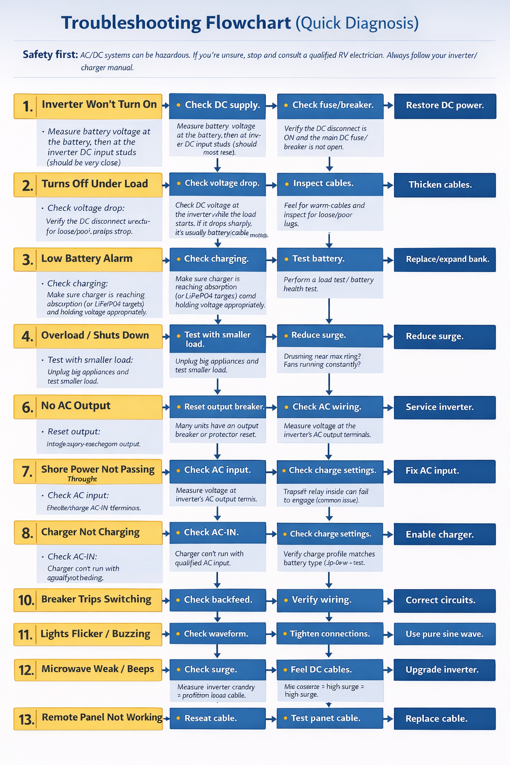
A) Troubleshooting Table
| Symptom | Most likely cause | Quick checks (in order) | Fix path |
|---|---|---|---|
| 1) Inverter won’t turn on | No DC power / disconnect off / blown fuse | Battery voltage at battery + at inverter DC studs | Turn on disconnect, replace fuse/breaker, correct polarity/terminals |
| 2) Inverter turns off under load | DC voltage sag from weak battery or cable voltage drop | Measure DC volts at inverter while load starts | Shorten/thicken cable, tighten lugs, improve battery bank; verify low-V cutoff per manual |
| 3) Low battery alarm quickly | Battery capacity low / aging / poor charging | Resting voltage, load test, check charger actually charging | Replace/expand bank; confirm charge settings and absorption targets |
| 4) “Overload” / shuts off with big appliance | Surge > inverter capability / wiring short | Try smaller load; unplug all loads; test one-by-one | Reduce surge loads, use soft-start appliances, correct wiring short |
| 5) “Overtemp” shutdown | Poor ventilation / high continuous load | Fan intake blocked? hot compartment? | Improve airflow, relocate, reduce continuous load |
| 6) No AC output (but inverter “on”) | Output breaker tripped / wiring issue | Check inverter output breaker/reset; measure AC at output terminals | Reset breaker, correct wiring, service if internal fault |
| 7) Shore power present but doesn’t pass through | Transfer relay not engaging / no AC input | Measure AC at inverter AC-IN terminals; verify input breaker | Fix upstream breaker/wiring; if AC present but no pass-through, relay/service |
| 8) Charger not charging batteries | Charger disabled / AC input missing / wrong battery settings | Confirm AC-IN, charger mode enabled, charge profile | Enable charger, correct profile (LiFePO4 vs lead), check temp sensor |
| 9) GFCI trips on inverter power | Neutral/ground bonding or leakage issue | Does it trip only on inverter? only one outlet? | Verify bonding behavior per inverter/charger manual/settings |
| 10) Breaker trips when switching shore↔inverter | Backfeed / miswired subpanel / transfer wiring | Confirm no inverter output tied into AC input | Correct wiring; isolate circuits; follow install guide troubleshooting |
| 11) Lights flicker / TV noise / “buzz” | Modified sine / poor grounding / loose connection | Try pure-sine source; check lugs/ground | Use pure sine for sensitive loads; tighten/clean connections |
| 12) Microwave runs weak / inverter beeps | Surge current + DC sag | DC volts at inverter during microwave start | Bigger inverter, thicker DC cable, stronger battery bank |
| 13) Remote panel not working | Cable/interference/connector | Reseat remote cable; route away from AC/DC bundles | Replace cable, improve routing |
| 14) DC fuse blows instantly | Polarity wrong / dead short on DC | Inspect polarity; isolate inverter DC leads | Correct polarity; inspect cable insulation; replace damaged parts |
| 15) Battery drains overnight | Phantom loads / inverter idle draw / mis-wiring | Measure DC current at rest; isolate circuits | Add disconnect strategy, reduce parasitic loads, schedule inverter off |
Troubleshooting Flowchart (Quick Diagnosis)
Safety first: AC/DC systems can be hazardous. If you’re unsure, stop and consult a qualified RV electrician. Always follow your inverter/charger manual.
1) Inverter won’t turn on
- Check DC supply: Measure battery voltage at the battery, then at the inverter DC input studs (should be very close).
- Check disconnect & fuse/breaker: Verify the DC disconnect is ON and the main DC fuse/breaker is not open.
- Check polarity: Confirm positive and negative are correct at the inverter.
Fix path: Restore DC supply, reset/replace fuse or breaker, correct polarity, retorque and clean terminals.
2) Inverter turns off under load
- Question: Does it happen only when a big load starts (microwave/compressor/pump)?
- Measure voltage sag: Check DC voltage at the inverter while the load starts. If it drops sharply, it’s usually battery/cable voltage drop.
- Feel/inspect cables: Warm cables or loose lugs are red flags.
Fix path: Shorten/thicken DC cables, improve terminations, strengthen battery bank, and confirm your inverter’s low-voltage cutoff behavior in the manual.
3) Low battery alarm happens quickly
- Question: Are batteries actually full before you start?
- Check charging: Confirm the charger reaches absorption/float (or LiFePO4 targets) and holds voltage appropriately.
- Capacity reality check: A small/aging bank will sag fast under inverter loads.
Fix path: Recharge fully, correct charge profile, test batteries, replace/expand bank if capacity is insufficient.
4) “Overload” or immediate shutdown with a big appliance
- Question: Does it work with small loads (phone/laptop) but fail with microwave/hair dryer?
- Isolate loads: Unplug everything and test one load at a time.
- Surge factor: Motor/compressor loads can exceed surge capacity.
Fix path: Reduce load, avoid high-surge devices, upgrade inverter size, or add soft-start where applicable.
5) Overtemperature shutdown
- Check airflow: Are vents blocked? Is the compartment hot?
- Check continuous load: Sustained near-max loads create heat.
- Fan behavior: Fans running constantly can indicate thermal stress.
Fix path: Improve ventilation, relocate inverter, reduce continuous load, keep intake/exhaust clear.
6) No AC output (inverter shows “ON”)
- Reset output breaker: Many units have an output breaker or protection reset.
- Measure AC at inverter output: If no voltage at the terminals, it may be an internal fault.
- Check wiring: Verify output wiring to outlets/subpanel is correct and not open.
Fix path: Reset breaker, correct wiring, service unit if internal fault persists.
7) Shore power present but no pass-through to outlets
- Check AC input: Measure voltage at the inverter/charger AC-IN terminals.
- Check upstream breaker: Shore pedestal breaker, RV main breaker, and any inline breakers.
- Transfer relay: If AC is present at AC-IN but not passing through, the transfer relay may not be engaging.
Fix path: Fix upstream AC feed first. If AC-IN is good but no pass-through, review installation guide tests and consider relay/service diagnosis.
8) Charger not charging batteries
- Confirm AC-IN: Charger can’t run without qualified AC input.
- Confirm charger enabled: Some remotes allow disabling charge.
- Battery profile: Wrong profile can limit charging (LiFePO4 vs lead-acid).
Fix path: Enable charger, correct profile, confirm charge current limits / load management, check temperature sensor if equipped.
9) GFCI trips when on inverter power
- Question: Does it trip only on inverter (not on shore)?
- Isolate circuits: Test with only one outlet/device connected.
- Bonding behavior: Some inverter/chargers bond neutral-to-earth only in inverter mode via an internal relay/settings; misconfiguration can cause nuisance trips.
Fix path: Follow your exact inverter/charger manual on neutral/earth bonding and ground relay settings. If uncertain, use a qualified electrician.
10) Breaker trips during shore ↔ inverter switching
- Backfeed check: Ensure inverter output is not feeding back into AC input (wiring error).
- Subpanel logic: Confirm only selected circuits are on the inverter subpanel (if used).
- Transfer wiring: Verify transfer switch/relay wiring matches the installation guide.
Fix path: Correct wiring, eliminate backfeed risk, re-check transfer/subpanel design per the installation guide.
11) Lights flicker / TV noise / buzzing
- Waveform check: Modified sine can cause noise with certain devices.
- Connection check: Loose DC lugs can create ripple and flicker.
- Load separation: Try separating sensitive electronics from motor/charger loads.
Fix path: Prefer pure sine for sensitive loads, tighten/clean connections, reroute wiring if interference is suspected.
12) Microwave weak / inverter beeps during microwave
- Question: Does DC voltage drop hard at startup?
- Check surge capacity: Microwaves often pull high surge/starting current.
- Check DC cable heating: Warm cables indicate undersizing or poor terminations.
Fix path: Upgrade inverter and/or battery bank, shorten/thicken DC cables, fix terminations.
13) Remote panel/display not working
- Reseat cable: Unplug/replug at both ends.
- Routing: Keep the remote/data cable away from high-current AC/DC runs to reduce interference.
- Test cable: Swap with a known-good cable if possible.
Fix path: Improve cable routing, replace damaged cable, confirm remote compatibility with model.
14) DC fuse blows instantly
- Polarity: Confirm positive/negative are not reversed.
- Dead short: Inspect DC cable insulation for abrasion and chassis contact.
- Isolation test: Disconnect inverter DC leads and test cable continuity to chassis (if qualified).
Fix path: Correct polarity, replace damaged cable/terminals, verify fuse class and rating per manufacturer guidance.
15) Battery drains overnight (even with small loads)
- Measure idle draw: Inverter standby consumption + phantom loads add up.
- Isolate circuits: Turn off breakers one-by-one to find parasitic drains.
- Check settings: Search mode/eco mode may reduce idle draw.
Fix path: Reduce parasitic loads, use a battery monitor, schedule inverter OFF when not needed, add a proper disconnect strategy.
Recommended Setups
3 build profiles (with “what it can/can’t run”)
Budget build: 1000–1500W pure sine (electronics + light kitchen)
Can run: laptop, router, TV, chargers, blender (small), small coffee maker (manage loads).
Can’t (reliably) run: microwave + other loads together; high surge appliances.
See 1500W pure sine inverter options on Amazon
Mid build: ~2000W class (microwave-friendly if the DC side is strong)
Can run: microwave in short bursts (if battery + cables are sized correctly), outlets, entertainment.
Can’t: roof AC, water heater element.
Full build: 3000W inverter/charger + subpanel
Can run: heavy kitchen bursts, multiple outlets, strong pass-through charging.
Can’t (usually): roof AC unless specifically engineered for soft-start + large battery bank + manufacturer guidance.
Disclosure reminder: prices and compatibility vary; verify against your RV’s electrical system and the inverter manual.
FAQ
What size inverter do you need for a microwave?
Most RV microwaves push you into the 2000W class, but success depends on battery voltage stability, not just inverter watts.
Is pure sine required for CPAP?
Often recommended. Check your CPAP power supply manual. If you want fewer surprises, pure sine is the safer default.
How close should the DC fuse be to the battery?
Best practice is as close as practical; a user-friendly target is the 12-inch golden rule, with industry guidance often referencing 7/40/72 style distances depending on routing protection.
Why does my inverter shut off under load?
Most commonly: DC voltage sag from long/undersized cables, weak batteries, or loose lugs. Confirm voltage at inverter terminals under load.
Why does GFCI trip on inverter power?
Often due to bonding/relay behavior or a downstream fault. Some inverter/chargers bond neutral to chassis in inverter mode via internal relays, which affects protection devices.
Can an inverter run while charging from shore power?
Many inverter/chargers can (pass-through + charge), but behavior is model-specific. Follow your manual.
Should you use a subpanel or whole-coach?
For most RVers, subpanel (selected circuits) is simpler, safer, and prevents accidentally powering huge loads.
What’s the #1 fire risk in RV inverter installs?
A long, unprotected high-current DC run and/or loose terminations. Put OCPD near the source and terminate correctly.
Do standards matter if you’re DIY?
Yes. In the USA, RVs commonly reference NFPA 1192 as a key safety standard, and Canada references CSA Z240 for RV electrical requirements.
Glossary + Reference Hub
Glossary (A–Z mini)
- AC: Alternating Current (shore/gen power).
- DC: Direct Current (battery power).
- GFCI/RCD: ground-fault protection device (regional naming differs).
- OCPD: fuse/breaker intended to protect conductors.
- Pass-through: inverter/charger routes input AC to output when available.
- Subpanel: selected circuits powered by inverter output.
“Always check your manual” references
- Manufacturer DC fuse + cable size tables: many brands explicitly publish these (use them). victronenergy.com
- Voltage-drop-based DC wire sizing: Blue Sea charts/tools are a solid method reference. bluesea.com
- Overcurrent protection placement rationale (7/40/72 style): practical references are widely published. bluesea.com